DILLIMAX 1100 Description
DILLIMAX 1100 is a high strength quenched and tempered, fine grained structural steel with a minimum yield strength of 1100 MPa (160 ksi)1) in its delivery condition ex works. Its mechanical properties are achieved by water quenching followed by tempering.
DILLIMAX 1100 is preferentially used for steel components if weight shall be reduced to a considerable extent, e.g. hoisting devices and cranes.
Designation and range of application
DILLIMAX 1100 can be delivered with the following dimensions according to the dimensional program. Other dimensions as larger widths e.g. for telescopic booms may be possible on request.
| Plate thickness t [mm] (in)a) | Width [mm] (in)a) | |
| ≥ 8.0 (0.3) | ≤ 9.5 (0.37) | 2500 (100) |
| > 9.5 (0.37) | ≤ 40 (1.6) | 3050 (120) |
a) The Values in brackets are for information only.
DILLIMAX 1100 Chemical composition
For the ladle analysis the following limiting values in % are applicable:
| C | Si | Mn | P | S | Cr | Ni | Mo | Ti | V+Nb | B |
| ≤ 0.18 | ≤ 0.50 | ≤ 1.60 | ≤ 0.015 | ≤ 0.005 | ≤ 2.00 | ≤ 3.5 | ≤ 0.70 | ≤ 0.01 | ≤ 0.10 | ≤ 0.004 |
The steel is fine grained through sufficient aluminium content.
Typical carbon equivalents CEV2) / CET3) are:
CEV = 0.78%
CET = 0.37%
DILLIMAX 1100 Delivery condition
Water quenched and tempered.
The Values in brackets are for information only.
2) CEV = C +Mn/6 +(Cr+Mo+V)/5 + (Cu+Ni)/15
3) CET = C +(Mn+Mo)/10 +(Cr+Cu)/20 + Ni/40
Mechanical and technological properties in the delivery condition
Tensile test at ambient temperature – transverse test specimens –
| Plate thickness Minimum elongation t [mm] (in.) a) | Tensile strength Rm [MPa] (ksi) a) | Minimum yield strength ReH b) [MPa] (ksi) a) | Minimum A5 [%] | elongation A2in.c) [%] |
| ≥ 8 (0.3) < 20 (0.8) | 1200 – 1500 | 10 | 11 | |
| ≥ 20 (0.8) ≤ 40 (1.6) | (175 – 220 ksi)1) | 1100 (160) | 8 | 9 |
a) The Values in brackets are for information only.
b) If not apparent, the yield strength Rp0.2 is measured instead.
c) These values apply if tested according to ASTM A370.
Impact test on Charpy-V-specimens
| DILLIMAX 1100 | Specimen direction | Impact energy Av in J (ft.-lb.) a) at test temperature of -40 °C (-40 °F)a) |
| High toughness | longitudinal / transverse | 30/27 (22/20) |
a)The Values in brackets are for information only.
An extra tough grade with guaranteed Charpy values at -60°C (-76 °F)4) may be agreed on request.
The specified minimum value is the average of 3 tests. One individual value may be below the minimum average value specified, provided that it is not less than 70 % of that value. For plate thicknesses below 12 mm (0.5 in) 4), the test can be carried out on Charpy-V test specimens with reduced width; the minimum width must be 5 mm (0.2 in) 4). The minimum impact value will be decreased proportionally.
DILLIMAX 1100 Testing
Tensile and impact tests will be performed on both ends of the heat treatment unit.
The specimens for the tensile test are prepared according to EN 10025-6. Testing is carried out on specimens of gauge length L0 = 5.65⋅√S0 or L0 = 5⋅d0, in accordance with EN ISO 6892-1. Tensile tests according to ASTM A370 may be agreed.
The impact test will be carried out on Charpy-V-specimens in accordance with EN ISO 148-1. Unless otherwise agreed, the test will be performed on transverse test specimens taken as follows:
- for plate thicknesses < 40 mm (1.6 in) 4): the test specimen shall be taken in such a way that one side is not further away than 2 mm (0.08 in)4) from a rolled surface.
- for plate thicknesses ≥ 40 mm (1.6 in) 4): ¼ of the plate thickness.
Unless otherwise agreed, the test results are documented in a certificate 3.1 in accordance with EN 10204.
DILLIMAX 1100 Marking
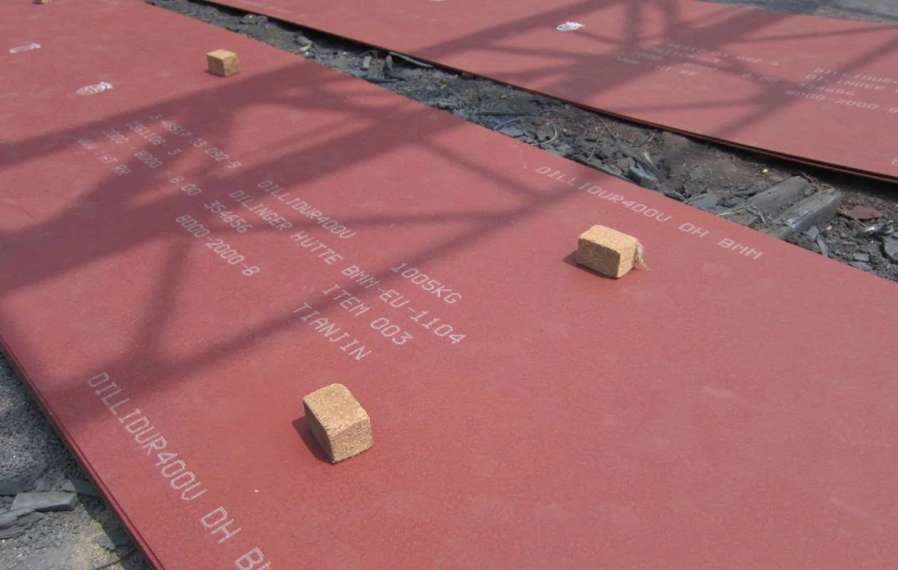
Unless otherwise agreed, the marking is carried out via low stress steel stamps with at least the following information:
- steel grade (DILLIMAX 1100)
- heat number
- number of mother plate and individual plate
- the manufacturer’s symbol
- authorized inspection representative’s sign
4) The values in brackets are for information only.
DILLIMAX 1100 Processing
The entire processing and application techniques are of fundamental importance to the reliability of the products made from this steel. The user should ensure that his design, construction and processing methods are aligned with the material, correspond to the state-of-the-art that the fabricator has to comply with and are suitable for the intended use. The customer is responsible for the selection of the material. The recommendations of the EN 1011 (Welding) and CEN/TR 10347 (Forming) as well as recommendations regarding job safety in accordance with national rules should be observed.
We recommend to consult us prior to the first working with DILLIMAX 1100. Detailed instructions for flame cutting, welding, machining and about the structural properties of the DILLIMAX are provided in the technical information “MAKE SAVINGS WITH HIGH STRENGTH STEELS – DILLIMAX”.
DILLIMAX 1100 Cold forming
DILLIMAX 1100 can be cold formed below 200 °C (390 °F)5) taking into account its high yield strength. Flame cut or sheared edges in the bending area should be ground before cold forming. It is also advisable to round the plate edge slightly on the outside of the bend coming under tension stress during bending.
Cold forming is always related to a hardening of the steel and a decrease in toughness. In contrast to lower yield strength steels DILLIMAX 1100 can not be heat treated at temperatures about 550°C(1022 °F)5) to reduce the strain hardening effects.
After higher cold forming amounts or if prescribed by regulations, a new quenching and tempering treatment may become necessary to restore the required mechanical properties. In this case, we recommend to consult us prior to ordering.
During the processing, the necessary safety measures have to be taken, so that nobody will be exposed to a danger by a possible fracture of the work piece during the forming process.
The following geometries can usually be achieved by cold forming without the formation of surface defects (where t is the plate thickness):
| Minimum bending radius | Minimum die width | |||
| Plate thickness t[mm] | < 20 mm (0.8 in) a) | ≥ 20 mm (0.8 in) a) | < 20 mm (0.8 in) a) | ≥ 20 mm (0.8 in) a) |
| Transverse direction | 4 t | 5 t | 12 t | 14 t |
| Longitudinal direction | 5 t | 6 t | 14 t | 16 t |
a) The Values in brackets are for information only.
Hot forming
If the temperature of 220 °C (428 °F)5) is exceeded, the initial tempering will be altered so that the mechanical properties are affected. To regain the initial properties new quenching and tempering become necessary. However, water quenching of a formed work piece or component will often be less effective than the original quenching in the plate mill so that the fabricator may not be able to reestablish the properties required. Therefore hot forming is not suitable.
Finally, it is the fabricator’s responsibility to obtain the required values of the steel through an appropriate heat treatment.
Flame cutting and welding
Due to its high yield strength, DILLIMAX 1100 requires special care during plate processing.
For flame cutting, the following minimum preheating temperatures are recommended: 75 °C (165 °F)5) for plate thickness up to 20 mm (0.8 in)5) and 125 °C (260 °F) 5) for plates thickness up to 40 mm
(1.6 in)5).
For general welding instructions, please consult the EN 1011-2. So far no welding consumables are available that produce tensile properties matching the base material. Thus, fully loaded joints must be avoided by an appropriate design. Minimum preheating, interpass and working temperature shall be limited to a range from 150 °C (302 °F)5) up to 200 °C (390 °F)5).
To avoid hydrogen-induced cold cracking, only filler materials which add very little hydrogen to the base metal may be used. Therefore, shielded arc welding should be preferred.
For manual arc welding, electrodes with basic coating (type HD < 5 ml / 100 g in accordance with ISO 3690), and dried according to the manufacturer’s instructions, should be used.
5) The values in brackets are for information only.
With increasing plate thickness, increasing hydrogen charge and restraint of the weld, a soaking for hydrogen effusion immediately after welding is recommended. The temperature for this treatment shall be in the range of 180 °C (355 °F)6) up to 220 °C (428 °F)6). To reduce hydrogen to an uncritical rate, we recommend the following holding times in the temperature range of 180 °C (355 °F)6) up to 220 °C (428 °F)6) (1 hour for welding joint thickness of up to 20 mm (0.8 in)6); 2 hours for welding joint thickness of up to 30 mm (1.18 in)6); and 4 hours for welding joint thickness of up to 40mm (1.6 in)6)).
A stress relief heat treatment is not possible and flame straightening is generally not permitted because these operations would reduce the tensile properties of the steel. Only in areas of the component where a local softening can be tolerated, straightening by flame or by inductive heating may be applied (in agreement with the design department).
General technical delivery requirements
Unless otherwise agreed, the general technical delivery requirements in accordance with EN 10021 apply.
Tolerances
Unless otherwise agreed, the tolerances will be in accordance with EN 10029, with class B for thickness and table 4, steel group H, for the maximum flatness deviation. Smaller flatness deviations may be possible on request prior to order (see specification DILLIMX TL for telescopic booms).
Surface quality
Unless otherwise agreed, the specifications will be in accordance with EN 10163-2, class B3.
General note
If particular requirements are demanded and not covered in this data sheet, please contact us with the specifications for our review and agreement prior to ordering. The information in this data sheet is a product description. This data sheet is updated at occasion demands. The latest version is available from the mill or as download at www.dillinger.de.
6) The values in brackets are for information only.
